one thing fixed (part 1)
 Comments(1)
… another thing breaks.
This is part of the laptop backlight repair documentation.
The main difficulty in replacing the CCFL is taking apart the laptop screen. I followed some of these references:
- This from here on how to open the lid portion that holds the screen.
- This from here on how to go the rest of the way to take apart the screen.
I didn’t take great pictures of the process but I took some.
The first steps are entirely straight-forward.
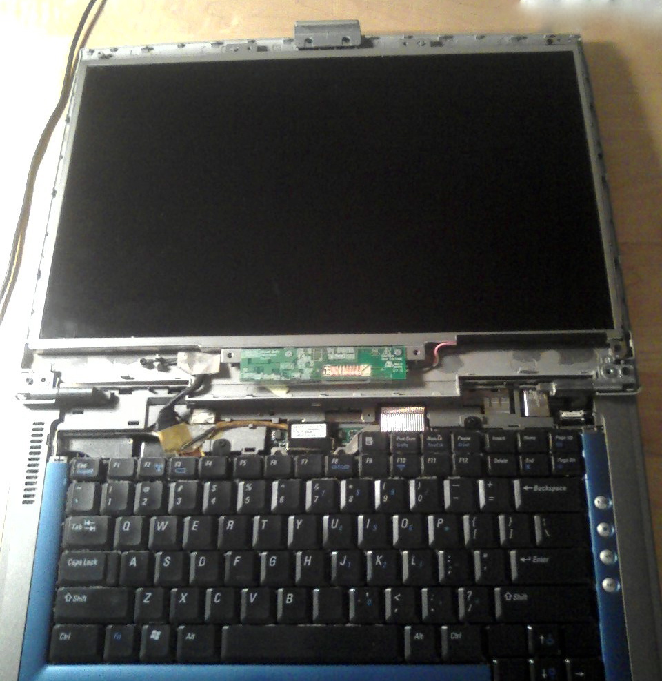
1. Removed the buttons panel and the lid panel
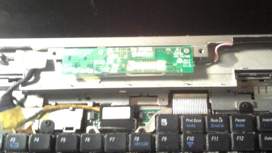
2. Closeup on the inverter and power supply board for the screen
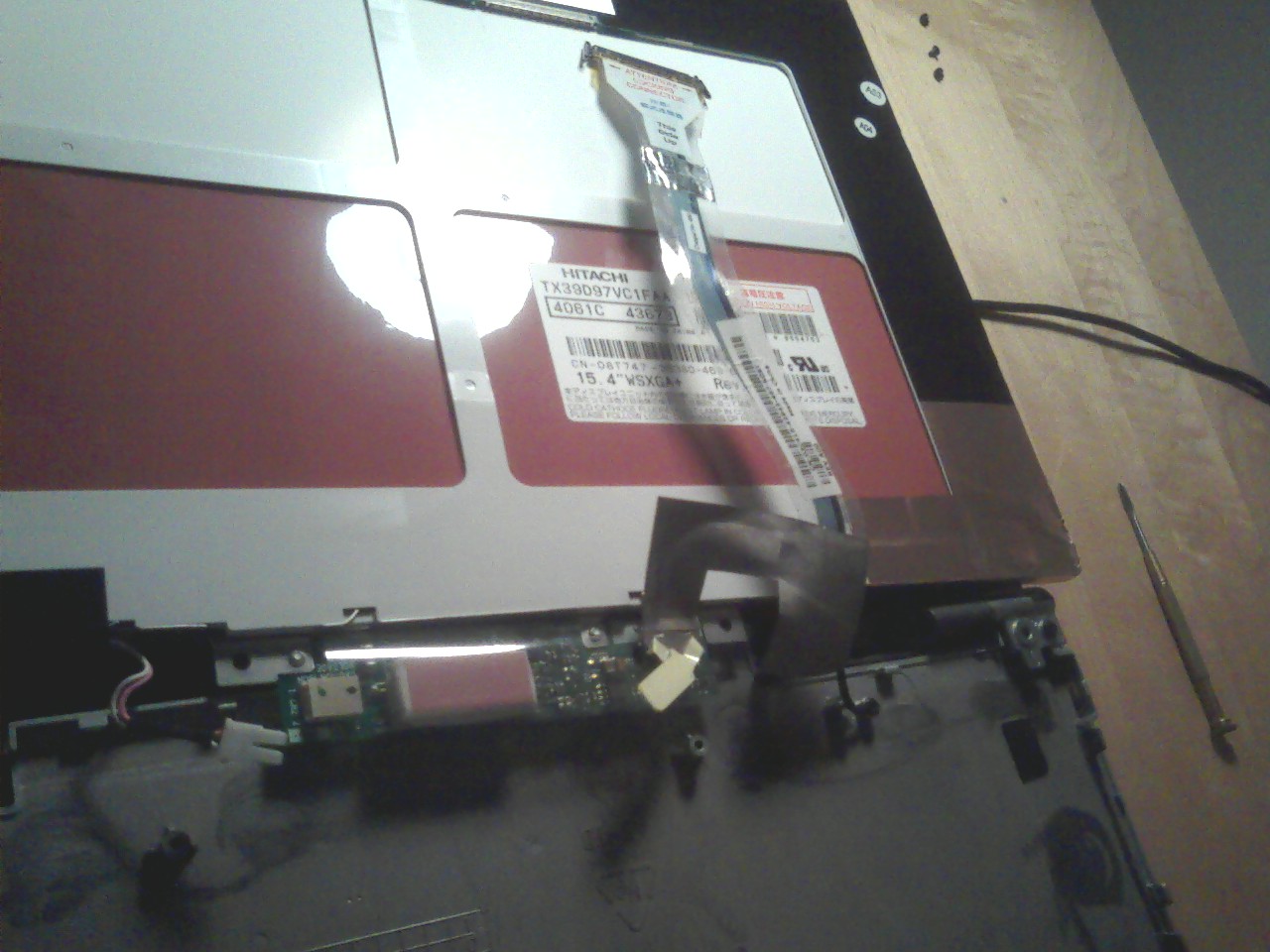
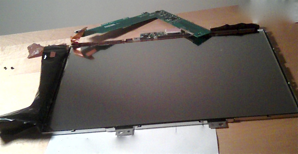
3. Back of the screen with CCFL power cable disconnected and liquid crystal color filter video cable disconnected
Now the screen is completely detached from the computer. If you buy a laptop screen replacement, this whole piece of thing will be replaced. But we keep going. The next steps are harder.
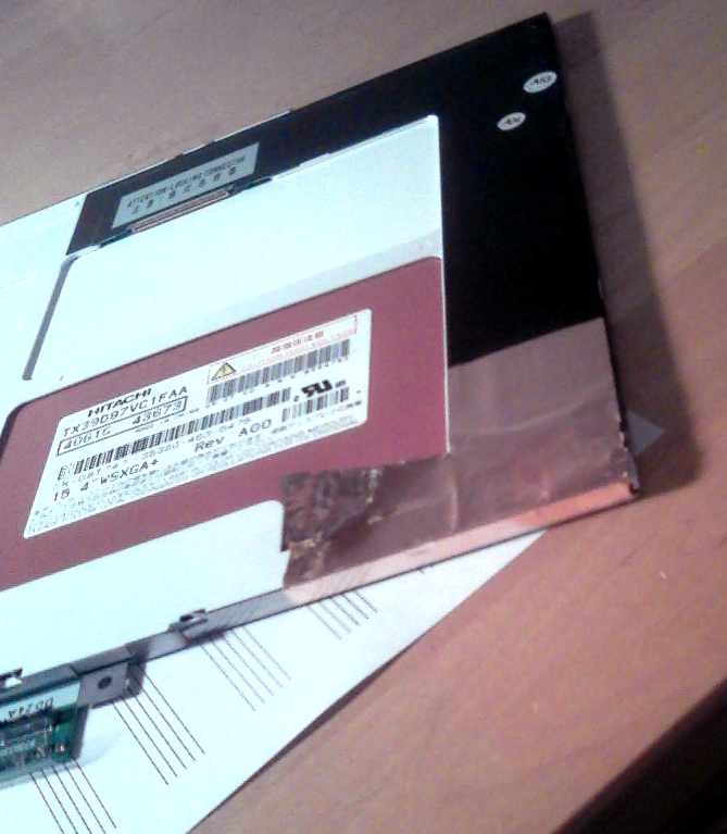
The screen is constructed in several layers. From the back to front are: the tape-held LCD controller board, a white-painted reflector sheet, a diffuser panel sitting in the CCFL slot, three transparent films for who knows what (polarizer?), then the liquid crystal color filter itself, finally a plastic protector screen.
4. Peeling back the sticky copper ground plane on the back. LCD controller board is underneath.
5. Here, all the tapes are peeled back: electric tape that holds the CCFL power cable, ground plane tape, and electric tape that holds the LCD controller board. The back layers up to the liquid crystal color filter have been removed.
6. The back layers and the front layers separated
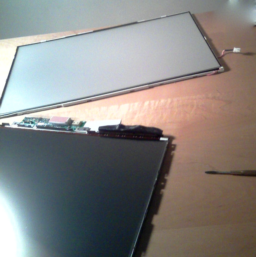
7. Back layers separated and CCFL slot removed. CCFL sitting inside
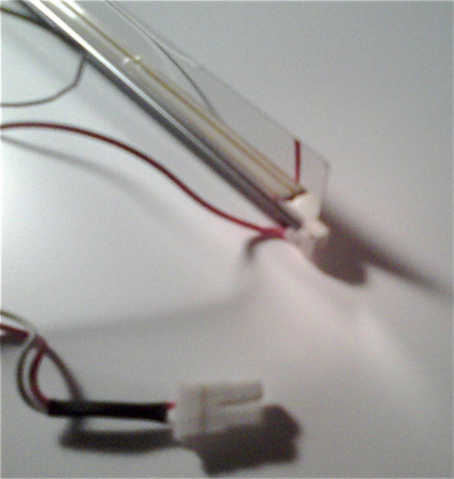
So I removed the rubber caps and took out the dying CCFL and realized the power cable is soldered on. Oops, I have no soldering iron at hand. Not to worry, I just turn the electric stove range to medium and solder away. I make sure to keep enough solder on the cable ends to put the new CCFL in. Clip the ends and done. Beautiful.
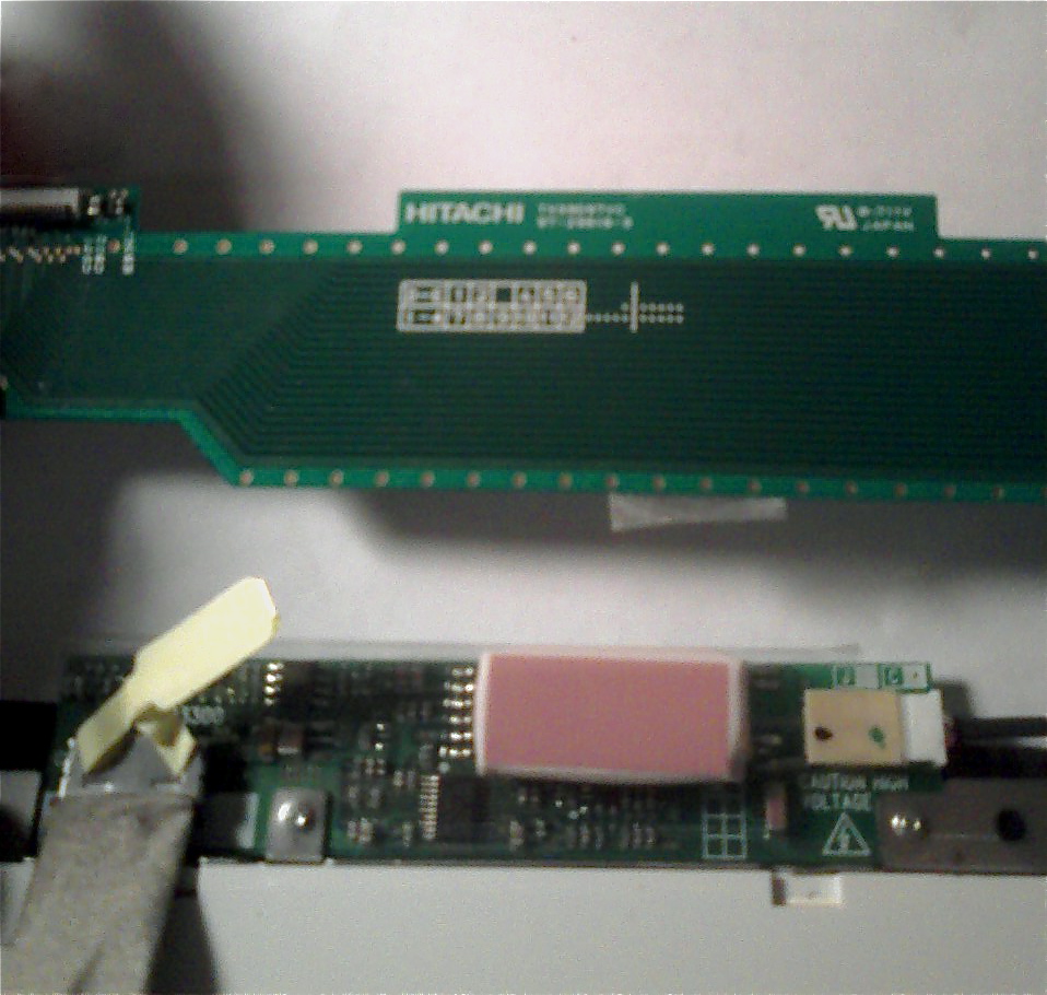
Then it was time to put everything back together. Now you’ll notice in 5 that the LCD controller board is attached to the liquid crystal color filter via a printed circuit film. There are two of these things and the wider one holds the data signal lines. They are latched in to the board, but somehow one was loose, and I had to push it back in to the controller board connector with some force. Then I put everything back together and turn on the computer and …
… I get a white screen. Not a black screen, but a white screen. So the new CCFL works perfectly, but the LCD died. After much inspection and disconnecting and reconnecting things on the controller board, I could only manage to get a few stray lines on the LCD. Sad. My best guess is the printed circuit film got bent out of shape or some traces inside broke. There was nothing I could do about it.
8. The controller board (top item) at a glance, with the connector in question on the left.
So back to square one.
On to Part 2.

[...] On to Part 1. November 10th 2008 Posted to Uncategorized [...]